
How to return the rear cover
|
|
Contains critical information. |

Check data port
Make sure that two O-rings are mounted on the data port. If only one o-ring is visible, contact customer support to arrange fitting a second o-ring.
Replace the Speed wheel
Remount the wheel on the PCB accordingly (same setting as previously)
Replace the cover
|
|
Slide the cover back on, ensuring that both brush wires are not pinched or folded, and are free to move after the cover has been replaced. If the wires catch on any housing, they will prevent the brush from sliding, which will eventually cause a spindle power failure. |
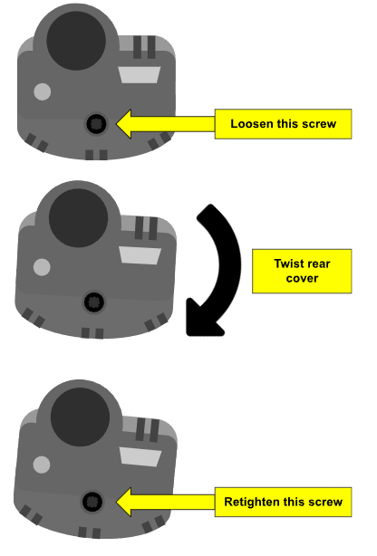
Using T20 Torx driver, re-tighten the retaining screw.
To confirm correct installation, loosen the rear cover screw, slightly twist the rear cover clockwise while holding the main body of the spindle motor then retighten the rear cover screw.
|
|
If the 2 O-rings on the speed port are present (as identified in the first section of this article), then the M8 thin hex nut (if present) need not be refitted. The second o-ring was introduced to constrain the PCB in the casing (via light compression), thus omitting the need for the M8 thin hex nut, which in turn speeds up rear cover removal for maintenance operations. |

Test
Power up the spindle. Click here to learn how to do that correctly.
A successful power up indicates that this procedure has been completed successfully.