
Y axis wheel setting procedure
Wheel setting rules and procedures
Tools required
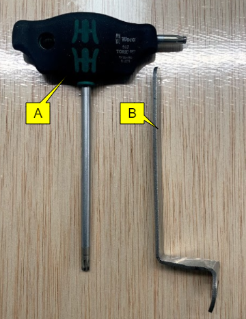
You will need the following tool for repair/maintenance:
A: T25 torx
B: Wheel adjustment spanner
Understand how to do wheel adjustment
|
|
Make sure the wheels are loose. You can also do this by slacken M5 torx screw with a T25 torx tool so the position can be changed. |

In general, to adjust the wheel position, hold the position of the M5 torx screws with a T25 torx tool and use a wheel adjuster spanner to change the position of the wheel.
Here is an example of how to change the position of a wheel from 180° to 90°.
The reference mark (A) describes the position of the wheel, here it's positioned at 180°.
A: Reference mark for wheel position

If not already, slacken the M5 torx screw by using a T25 torx tool.
B: M5 torx screw
C:T25 torx tool

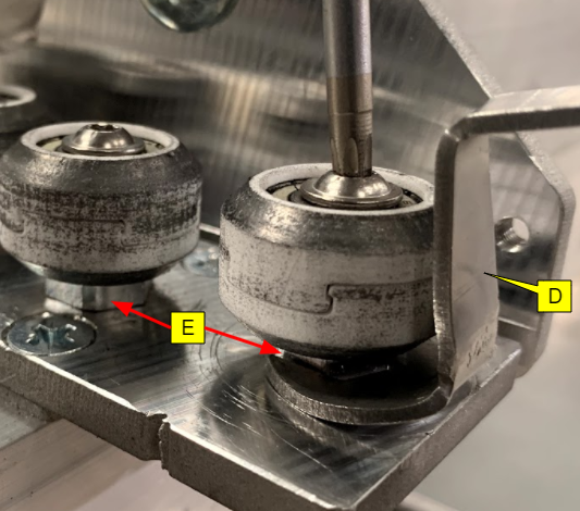
Fit the wheel adjustment spanner to the bearing adjuster as shown in the image.
D: Wheel adjustment spanner
E: Bearing adjuster
Hold the position of the T25 torx tool and only rotate the wheel adjustment spanner.
F:T25 torx tool
G: Wheel adjustment spanner
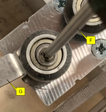
By rotating the wheel adjustment spanner only you can change the position of the wheel, for example, we have gone from 180° to 90° (by rotating anti-clockwise).
F:T25 torx tool
G: Wheel adjustment spanner

Once you are happy with the position of your wheel, tighten the M5 torx screw with a T25 torx tool and this time hold the position of the wheel adjustment spanner to lock the wheel in position.
F:T25 torx tool
G: Wheel adjustment spanner

This is how the position of the wheel looked at 90°.
A: Reference mark for wheel position

|
|
Repeat the above procedure to change the position of the wheels. |
Step 1: Setting the initial wheel position
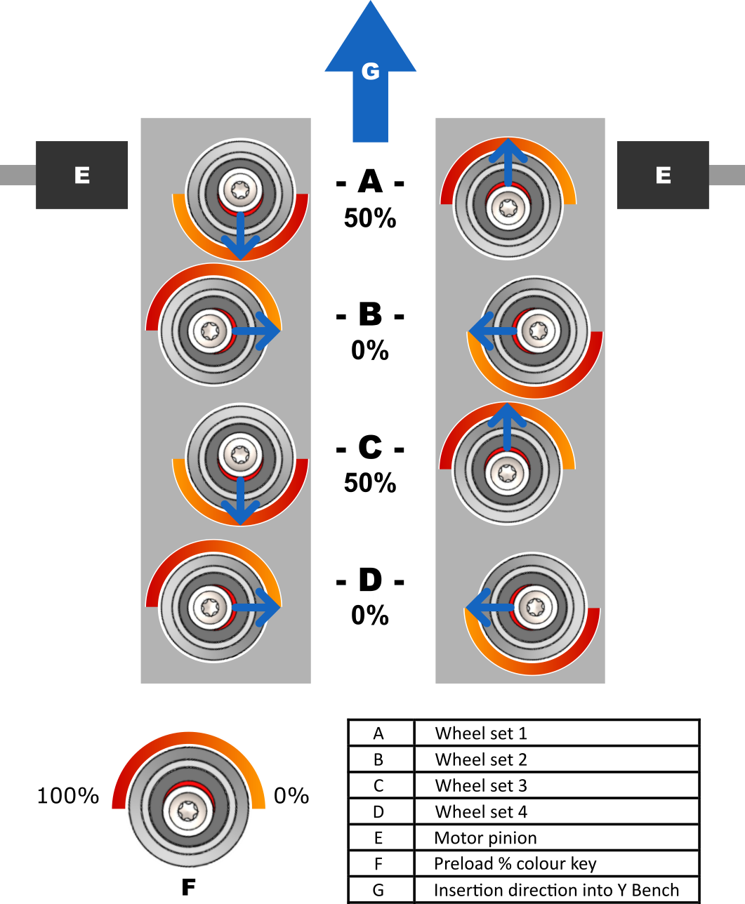
Before setting wheels, position them according to the chart shown below. We have also given an identity to the wheels, for example, 1st row wheels are called wheel set one, 2nd row wheels are called wheel set two, etc.
|
|
When setting Y wheels, always start with this chart and position your wheels accordingly. |

Step 2: Set preload on wheel set 1
Before loading the wheels make sure the motor pinions are not engaged with the racks as was discussed in the Lower Beam preparation article.

Move the cam to ensure that both sides have an equal amount of preload. When you insert the beam, a light pop will ensure the correct fitting.
Check the following:
-
Insert the Lower X Beam into the channels and feel the resistance.
-
If you feel too much resistance, then you have to reduce the preload by slightly rotating the cam clockwise away from the channel wall.
H: Wheelset 1

Step 3: Set preload on wheel set 3
After setting preload on wheel set 1, skip wheelset 2 for now, move on to wheel set 3 and apply the same principles as you have done for wheel set 1.
H: Wheel set 1
J: Wheel set 3

Check for squareness
When checking for squareness against the Lower X Beam plate, pull the beam from the centre and align both the Y Bench and Lower X Beam plate so that they are parallel
If both left and right plates match then you have achieved squareness.

If either of the wheel plates doesn’t match, for example in the image below, the right side plate is sitting slightly proud of the Y Bench end plate compared to the left side plate.
If you encounter this issue or vice versa then you have to do minor “equal and opposite” adjustments on wheel set 3 which you have preloaded.
A general rule of thumb is:
-
If the side is minus: reduce preload on that wheel
-
If the side is plus: add preload on that wheel
-
Do an equal and opposite adjustment to the other side to maintain preload
For the case below:
-
On the right side plate (plus): add preload on wheel 3 for that side only.
-
On the left side plate (minus): reduce preload on wheel 3 for that side only.
-
Then check the beam for alignment. If the plates align then proceed to step 4 or keep doing the adjustments until both the plates are aligned.

Step 4: Set preload on wheel set 2
Now we will apply preload on wheel set 2, note that they run on the outside of the channel. Also when you apply preload on wheel set 2, it's likely that the preloaded wheel set 3 might be hard to get into the channels. If so, reduce the preload by small, equal amounts on both sides of wheel set 3 until you can insert into the Lower X Beam without needing excessive force.
H: Wheel set 1
I: Wheel set 2
J: Wheel set 3

Check approach on wheel set 3
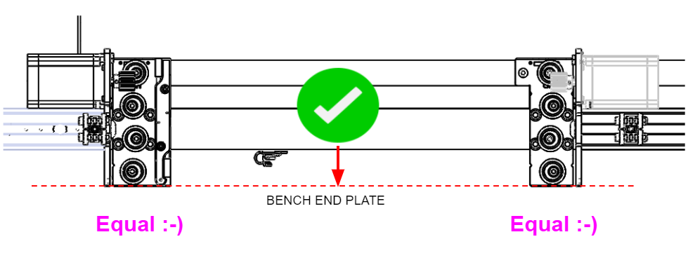
Once preload is added on wheel set 2, you need to check if both wheel set 3 axle bolt centres approach the bench end plate at the same time as shown in the image.


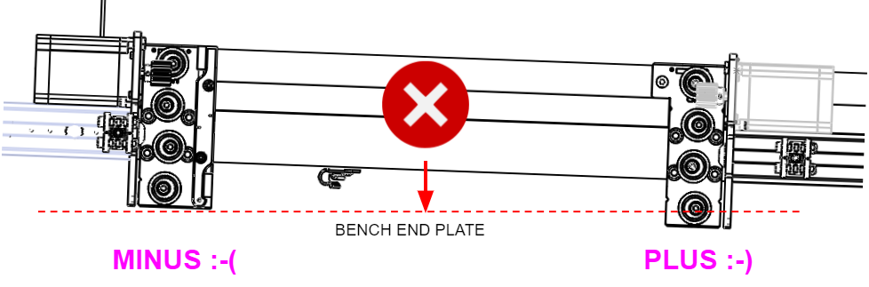
If either of the bolt centres do not approach at the same time, for example, in the image below, the left side bolt enters the channel before the right side, then you have to do minor “equal and opposite” adjustments on wheel set 2.
|
|
Note this setting is opposite to squareness. |

A general rule of thumb is:
-
If the bolt centre is minus: add preload on the wheel set 2 on this side
-
If the bolt centre is plus: reduce preload on the wheel 2 on this side
For the case below:
-
On the right side bolt (plus): reduce preload on wheel set 2.
-
On the left side bolt (minus): add preload on wheel set 2.
-
And check the bolts centre for approach. If both the bolts centres enter the bench end plate at the same time then proceed to step 4 or keep doing the adjustments until both the bolt centres approach is the same.


Step 5: Re-set preload on wheel set 3
Once you are happy with the bolt centre approach on wheel set 3, the next step is to check the beam plate for squareness as we did after setting the initial preload on wheel set 3. Follow the same procedure as mentioned in the check for squareness section.
|
|
Do not change the setting on either wheelset 1 and 2. |
Step 6: Set preload on wheel set 4
To set preload on wheel set 4, simply insert the Lower X Beam into the channels so that your finger can access the wheel for rotation. Initially the wheels will rotate as they were set for zero preload.


Start applying preload on wheel set 4 as shown in the image.
H: Wheel set 1
I: Wheel set 2
J: Wheel set 3
K: Wheel set 4

If you can insert the Lower X Beam by using your thumbs (and feel slight resistance) this indicates adequate preload.

Once you have applied the preload, check whether the wheel set 4 spins or not with your thumb. If it does then you have to slightly increase the preload by an equal amount on both sides and re-check for spin.
|
|
Do not change the setting on either wheel set 1, 2 and 3. |

Check for squareness
Once you are happy with the preload on wheel set 4, the next step is to check the beam plate for squareness. Usually this will be set but if not then follow the same procedure as mentioned in the check for squareness section and only adjust preload on wheel set 4.
|
|
Don’t change the setting on either wheel set 1, 2 and 3. |
Step 7: Lock the motor in position
Once you have finished setting the wheels, you will need to rotate the pinions back into the racks.
Rotate the motor pinions on both sides of the lower beam to mesh with the racks.
L: Lower beam motor

Hold and tighten off the 4mm hex socket at the top of the motor on both sides of the beam.

Raise the motor pinion and tighten the hex bolt by using a 10mm spanner on both sides of the beam.
M: 10mm bolt

As an indication, if the motor is raised (as shown in the picture below) this means the pinions are meshing into the racks.

Step 8: After procedure checklist
Once you are happy with the setting of the Lower X Beam you can carry on fitting other components of the SmartBench by clicking here and continue enjoying smart machining.
|
|
If you need any assistance with the wheel replacement process then submit a support ticket by clicking here. |