
BigFoot Beta installation guide
Introduction
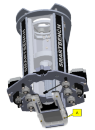
To install BigFoot on your Z Head you will first need to remove the dust shoe already attached to your Z Head.
A: Dust shoe
B: BigFoot

The steps involved in installing BigFoot are as follows:
-
Firstly, identify the version of your Z Head
-
Then we’ll remove the old dust shoe
-
Install Bigfoot on your Z Head.
Procedure
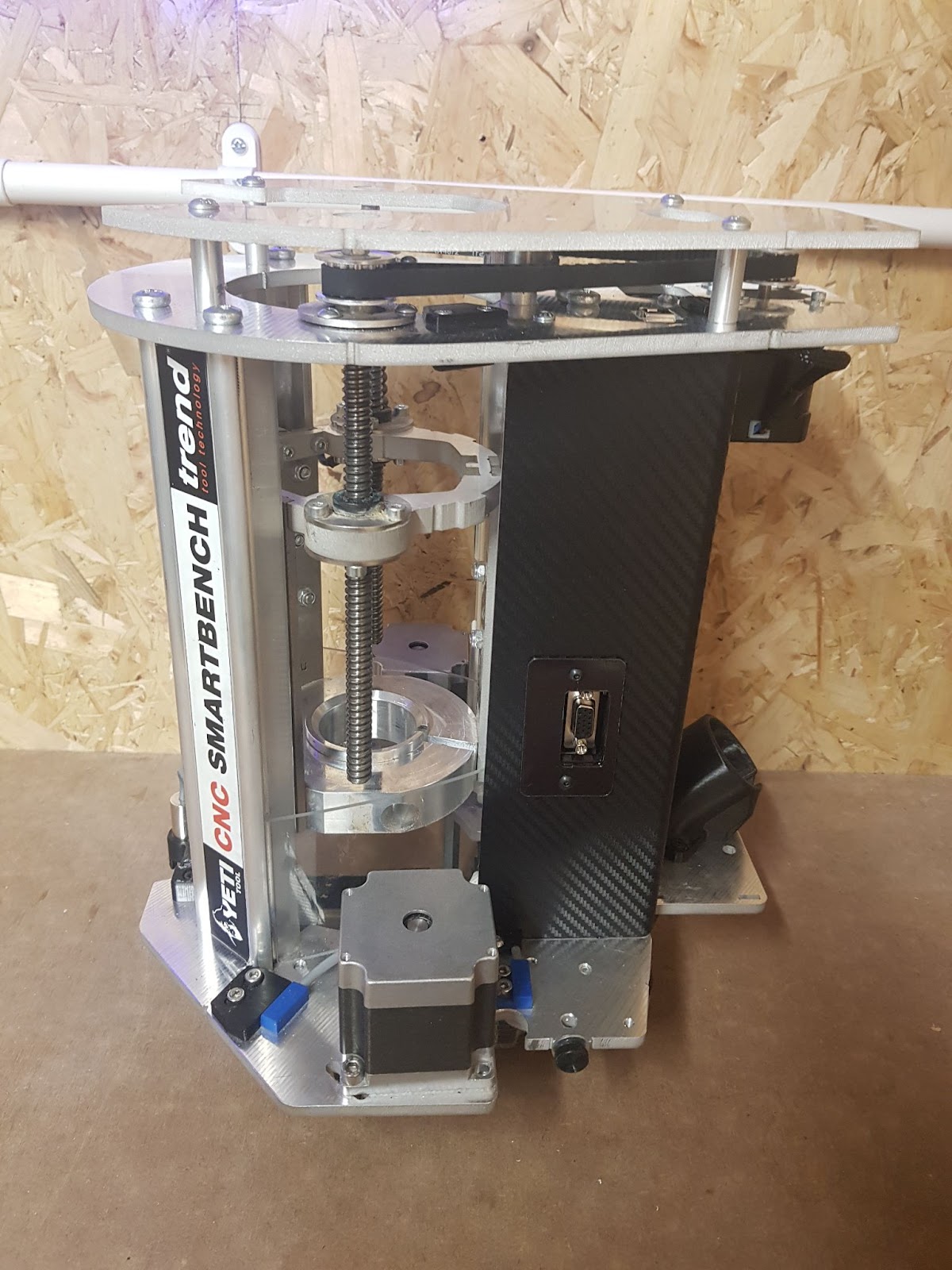
Step 1: Identify the version of your Z Head
Here is an example 1.1 or a 1.2a


Here is an example 1.2b or 1.3


Step 2: Remove your existing dust shoe
Once you have identified your Z Head version, click on the link below which is most relevant to you.
Z Head 1.1 or 1.2a dust shoe removal
Z Head 1.2b or 1.3 dust shoe removal
Step 3: Installing BigFoot
Step 3.1: Tools required
You will need the following tools:
A: 2.5mm hex driver
B: 3mm hex driver
C: flat head screwdriver or 7mm hex socket
D: pliers
Step 3.2: Attaching BigFoot to the Z Head
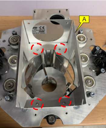
Position the Z Head as shown in the image (upside down).

Remove the two screws highlighted in the image on the BigFoot by using a 2.5mm hex driver and lift off the bottom plate.


We will be aligning the BigFoot to these four holes highlighted in the image.

Align BigFoot to these four holes.
A: BigFoot
And use four M4x6 screws to attach BigFoot to the Z Head by using a 2.5mm hex driver.

Re-attach the removed bottom plate with the two M4x6 screws by using a 2.5mm hex driver as shown in the image.


Your BigFoot is now installed.

Step 3.3: Assembling BigFoot to SmartBench
Install Z Head to the Upper Beam as shown in the picture
|
|
Make sure the signal and power cables are connected to the Z Head first so that they avoid damage. |


Connect the extraction pipe to the Z Head.

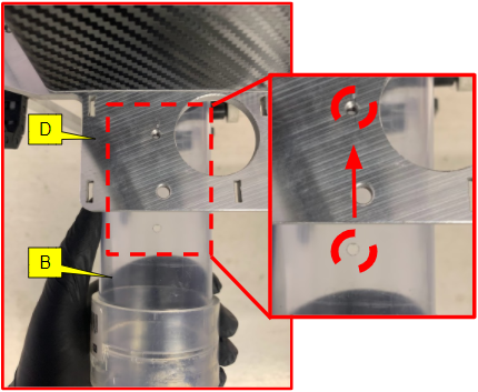
Insert the extraction pipe (B) to the BigFoot (A) till the connector (C) touches the Z Head bottom plate (D).
A: BigFoot
B: Extraction pipe
C: Connector
D: Z Head bottom plate
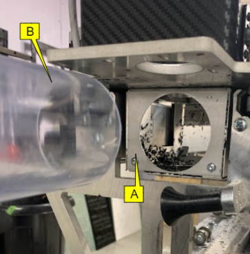

And make sure the hole on the pipe is aligned with the hole on the Z Head bottom plate as shown in the image below.
B: Extraction pipe
D: Z Head bottom plate
Your extraction pipe will be suspended as shown in the image.
B: Extraction pipe

Use the two cable ties (provided in the kit) to secure the connection of the pipe with the Z Head “Do not tighten the cable ties at this stage”.
|
|
Make sure the locking head (F) of the cable ties is below the Z Head bottom plate. |
D: Z Head bottom plate
E: Jubliee Clips (Photos to be updated) The Head of the Jubliee clips needs to remain on the same side as the photographed Zip-Ties - e.g. left on this photo
F: Cable ties locking head

Make sure you have the extraction pipe connector touching the Z Head bottom plate.
C: Connector
D: Z Head bottom plate

Insert screw provided in the kit (tighten the screw with your hand).
|
|
The screw will keep the hole position of the extraction pipe and the Z Head bottom plate in the same place while we tighten the zip ties. |
G: M4x16

Tighten the cable ties by using a plier and trim of the excess.
E: Cable ties

Prepare the extraction hose by inserting jubilee clips to both ends of the hose
H: Extraction hose
I: Jubilee clips

Fit the extraction hose to the extraction pipe.
B: Extraction pipe
H: Extraction hose

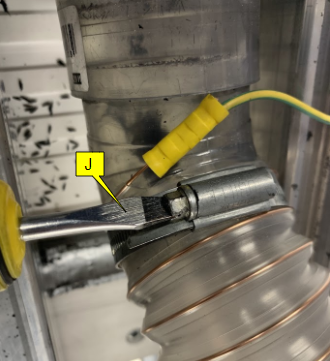
And secure it by tightening the jubilee clips using a flat head screwdriver or 7mm hex socket.
J: Flat head screwdriver or 7mm hex socket
Connect the earthing wire (attached on the ends of the extraction hose) to the Z Head bottom plate with a screw (shown in the image) found in the packaging (you will need a 2.5mm hex driver).
K: M4x6
D: Z Head bottom plate
L: Earthing wire
Remove the screw that was inserted earlier (keep the screw safe as it will be used in the final step)
G: M4x16

Place the bottom plate first followed by the top plate as shown in the images.
M: Bottom plate

N: Top plate

Secure the plates and the extraction pipe with a screw (which was removed earlier), also make sure the screw goes into the hole of the extraction pipe. Use another screw found in the packaging to firmly secure both the plates.
G: M4x16
O: M4x10

Connect the other end of the extraction hose to your extraction system inlet and make sure to connect the earthing cable so the whole system is earthed to prevent static buildup in the hose.
|
|
If your extraction inlet size is bigger than the diameter of the extraction hose supplied, use a suitable adapter. Adapter for Ø100-Ø63mm is supplied with the kit. |
L: Earthing cable
P: Adapter (Ø100-Ø63mm)


Finally, fit the plug plate to the front of the BigFoot by aligning the magnets with the holes in the Bigfoot body.
Q: Plug plate


|
|
If you need any assistance with the BigFoot installation process then submit a support ticket by clicking here. |