Fitting the Upper X Beam
You will need
-
Upper X Beam

Installing the Upper X Beam
The Upper X Beam consists of the track that the Z Head moves along, and two stop bars.
Note the home icon on one of the inner faces of the Upper X Beam.
A: Wheel channels for the Z Head
B: Stop bar

Prior to installing the Upper X Beam, the assembly of the Y Bench and the Lower X Beam should look like this:
C: Y Bench
D: Lower X Beam

Before you begin, ensure the clamp handles on the ends of the Lower X Beam are in an upright (open) position.

Lift the Upper X Beam onto the Y Bench.
Ensure that the Home label on the inside of the Upper X Beam is facing the same direction as the Home label on the Y Bench.

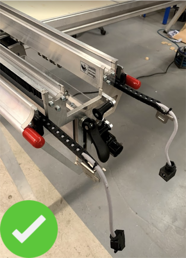
Position the Upper X Beam so that the link cable (E) is on the same side as the stop button (F) on the Lower X Beam
E: Upper X Beam link cable
F: Lower X Beam stop button

Align the Upper X Beam so the forks on each end slide over the clamp bolts, parallel to the skids of the Lower X Beam:
G: Forks on the end of the Upper X Beam
H: Clamp bolts
I: Skids

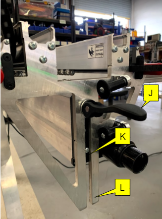
The fitting should look like this:
J: Clamp handle
K: Skids
L: Forks on the end of the Upper X Beam
Secure the beam in place by pushing the clamp handles down.
|
|
Do not twist the handle as this will change the clamping settings. |

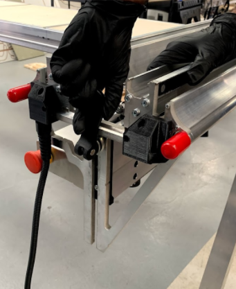

The clamp handles will close at an angle when they are tight. This is to enable easy access to unclamp.

Leave the handles in the downside position.
|
|
Do not twist the handle as this will change the clamping settings. |


The drag chain latch plates are on the far end of the Upper X Beam:
M: Drag chain latch plates
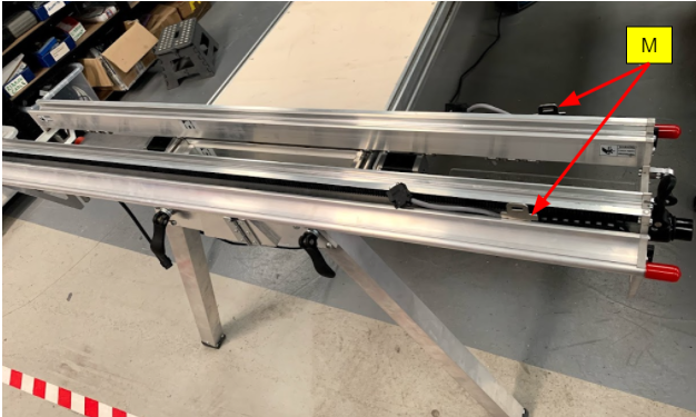
Slide the cables out by pulling the drag chain latch plates.
N: Power cable
O: Drag chain latch plates
P: Signal cable

Pull out the Z head power and signal cables so that they are laid flat and extend from the end of the Upper X Beam.
Q: Power cable
R: Latch plate
S: Signal cable

The drag chain latch plates, power and signal cables will all attach to the Z Head in the next part of the assembly.